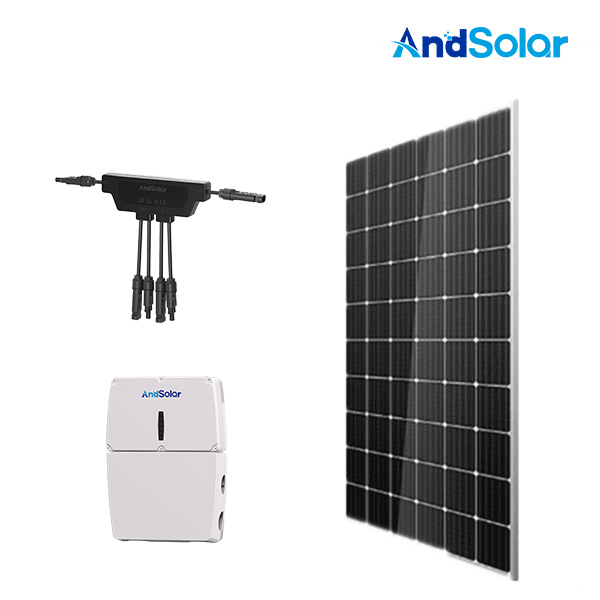
Smart PV modules and shutdown optimizers represent a critical advancement in rooftop solar system design, offering enhanced safety and performance monitoring at the module level. Understanding how to properly wire smart PV modules and shutdown optimizers is essential for installers, electricians, and system designers who want to maximize both safety and energy production. Improper wiring of smart PV modules and shutdown optimizers can compromise system reliability, create safety hazards, and reduce monitoring accuracy across your entire installation.
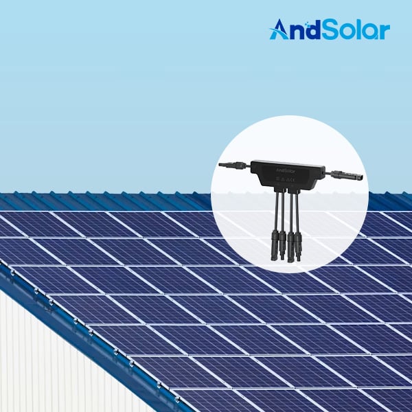
The integration of smart PV modules and shutdown optimizers into rooftop solar installations requires a systematic approach that combines electrical safety principles with modern monitoring architecture. These components work together to provide real-time data collection, rapid shutdown capability, and module-level performance tracking. Proper wiring methodology ensures that smart PV modules and shutdown optimizers communicate effectively with your string inverters and monitoring systems while maintaining full compliance with national electrical codes and manufacturer specifications.
Understanding Smart PV Modules and Shutdown Optimizers Architecture
Core Components and Function
Smart PV modules and shutdown optimizers function as integrated power conditioning and communication devices that sit between your solar modules and the main inverter system. Each unit handles DC optimization at the module level, reducing power losses from mismatch and shading while simultaneously collecting performance data. When you integrate smart PV modules and shutdown optimizers into a rooftop solar setup, you enable per-module voltage and current monitoring, which significantly improves system diagnostics and fault detection capabilities.
The architecture of smart PV modules and shutdown optimizers typically includes built-in DC disconnect functionality, allowing rapid power shutdown to meet safety requirements during maintenance or emergencies. This integrated shutdown capability means that smart PV modules and shutdown optimizers must be wired in a configuration that allows the central inverter or monitoring system to communicate shutdown signals to each device simultaneously. Understanding this communication pathway is fundamental to correct installation and long-term system reliability.
Safety and Performance Integration
Safety considerations drive the wiring methodology for smart PV modules and shutdown optimizers in any rooftop solar installation. The rapid shutdown requirement, mandated by the National Electrical Code Article 690, specifies that PV systems must be able to reduce open-circuit voltage to safe levels within thirty seconds when a shutdown signal is sent. Smart PV modules and shutdown optimizers meet this requirement through integrated electronics that respond to communication signals from the combiner box or inverter. Proper wiring ensures that shutdown commands propagate immediately to all smart PV modules and shutdown optimizers on the roof.
Performance monitoring relies on bidirectional communication pathways embedded within the smart PV modules and shutdown optimizers. These devices transmit real-time data about voltage, current, temperature, and fault conditions back to your monitoring platform. Correct wiring preserves signal integrity, reduces noise interference, and ensures that smart PV modules and shutdown optimizers deliver accurate performance metrics throughout the installation lifecycle.
Wiring Configuration for String Integration
Series String Assembly
Smart PV modules and shutdown optimizers must be wired in series strings that connect multiple modules into a single electrical path leading to your string inverter. In a typical rooftop solar installation, each string contains eight to fourteen modules depending on voltage requirements and system design. When wiring smart PV modules and shutdown optimizers in series configuration, the positive output of one device connects to the negative input of the next device, creating a continuous chain that maintains proper voltage accumulation.
The connection points between smart PV modules and shutdown optimizers require properly rated DC connectors, typically MC4 or equivalent connectors rated for your system voltage and current. Each connection must be mechanically and electrically secure, with proper contact pressure to minimize resistance and heat generation. Poor connections between smart PV modules and shutdown optimizers represent a leading cause of performance degradation and can create fire hazards if left unchecked. All connectors must be rated for outdoor use, UV resistant, and compatible with the voltage levels present in your specific configuration.
String Combiner and Monitoring Interface
Multiple strings of smart PV modules and shutdown optimizers converge at a string combiner unit, which aggregates power from each string and routes it to the central inverter. The combiner box serves as the control hub where shutdown commands originate when needed. Smart PV modules and shutdown optimizers in each string must receive these commands through dedicated communication lines, which are typically low-voltage twisted-pair or fiber optic cables. Proper grounding and shielding of communication lines prevent signal corruption and ensure reliable command delivery to all smart PV modules and shutdown optimizers across your installation.
The monitoring interface layer connects your smart PV modules and shutdown optimizers to cloud-based or on-site monitoring systems, enabling real-time data visualization and predictive maintenance alerts. Installation of smart PV modules and shutdown optimizers requires integration with your system's data acquisition hardware, which must support the communication protocol used by your specific devices. Ethernet, RS-485, or proprietary wireless protocols are common in modern smart PV modules and shutdown optimizers, so your combiner unit must include compatible interfaces.
Safety Compliance and Grounding Requirements
Rapid Shutdown and Disconnect Wiring
The rapid shutdown circuit is a mandatory safety component that works hand-in-hand with your smart PV modules and shutdown optimizers. This dedicated wiring pathway allows system controllers to command all smart PV modules and shutdown optimizers to enter a safe state within the required thirty-second timeframe. The shutdown pathway typically runs from your monitoring controller or inverter, through the combiner box, and out to each string via a low-voltage control line. Every string containing smart PV modules and shutdown optimizers must have a dedicated shutdown line to ensure simultaneous response across all devices.
The wiring of smart PV modules and shutdown optimizers for rapid shutdown must meet specific isolation requirements to prevent accidental triggering during normal operation. The control lines carrying shutdown signals must be physically separated from main power conductors and properly color-coded according to electrical code. Ground-fault protection must be coordinated between the smart PV modules and shutdown optimizers and any additional DC disconnect or rapid shutdown components in your system to prevent nuisance trips while maintaining protection against genuine ground faults.
Grounding and Equipment Bonding
Proper grounding of smart PV modules and shutdown optimizers ensures electrical safety and protects equipment from lightning strikes and transient overvoltages common in rooftop environments. Each array location containing smart PV modules and shutdown optimizers must have dedicated equipment grounding conductors that tie all metal frames and housings to the system ground. These grounding conductors must be sized according to the main system overcurrent protection devices and must not be interrupted by disconnects or monitoring equipment. Smart PV modules and shutdown optimizers with metal housings require mechanical bonding to the grounding system, typically through copper lugs and stainless steel hardware rated for outdoor UV exposure.
Communication lines connecting your smart PV modules and shutdown optimizers must also maintain proper grounding to prevent high-frequency noise that corrupts data signals. Twisted-pair shielded cables carrying low-voltage control signals should have their shields grounded at one point to drain common-mode noise while preventing ground loops. smart PV modules and shutdown optimizers installations must follow manufacturer specifications for grounding practices specific to each device model. Failure to implement proper grounding reduces system reliability and can create potential safety issues during maintenance.
Installation Best Practices and Troubleshooting
Cable Routing and Environmental Protection
Routing DC power and communication cables for smart PV modules and shutdown optimizers requires careful planning to protect wires from physical damage, UV degradation, and thermal stress. Main DC power conductors should be routed through conduit rated for solar applications, with separate conduit or cable trays for communication lines to prevent electromagnetic interference. When running smart PV modules and shutdown optimizers communication cables across your rooftop, use UV-resistant wire sleeves and secure cables at regular intervals to prevent wind-related movement and abrasion. All exposed connectors on smart PV modules and shutdown optimizers must be protected with weatherproof boots and sealed with dielectric grease to prevent corrosion.
Temperature management around smart PV modules and shutdown optimizers directly affects performance and longevity. Ensure adequate ventilation around all devices, avoiding installation scenarios where smart PV modules and shutdown optimizers sit in direct sunlight without air circulation. Cable sizing must account for the maximum current conditions plus safety margins, ensuring that smart PV modules and shutdown optimizers operate within specified thermal limits throughout their service life. Undersized wiring creates excessive heat that accelerates component failure and degrades system reliability.
Testing and Verification Procedures
After wiring your smart PV modules and shutdown optimizers installation, comprehensive testing verifies that all connections are secure and all systems operate as designed. Continuity testing confirms that power conductors properly connect each device in series while isolation testing validates that no unintended connections exist between power circuits and grounding conductors. Smart PV modules and shutdown optimizers must respond correctly to test shutdown signals, with voltage measurements confirming that all devices reach safe levels within the required timeframe.
Communication testing ensures that monitoring data flows correctly from every smart PV modules and shutdown optimizers unit to your central monitoring platform. Visual inspection of all connections, connectors, and cable entries on your smart PV modules and shutdown optimizers should reveal no signs of corrosion, loose terminals, or improper seating. Documentation of all testing results creates a baseline for future maintenance and enables rapid diagnosis if smart PV modules and shutdown optimizers performance degrades unexpectedly.
FAQ
What voltage levels should I use when wiring smart PV modules and shutdown optimizers?
Voltage levels for smart PV modules and shutdown optimizers depend on your system configuration and inverter specifications, typically ranging from 400 to 1000 volts DC. Most residential installations using smart PV modules and shutdown optimizers operate between 400 and 600 volts, while commercial systems may reach higher voltages. Your system designer and inverter manufacturer must specify the exact voltage configuration, and all string assembly decisions should reflect this voltage target. Smart PV modules and shutdown optimizers are rated for specific voltage ranges, so mixing devices across incompatible voltage classes can damage equipment.
How do communication lines connect between smart PV modules and shutdown optimizers and the monitoring system?
Communication lines for smart PV modules and shutdown optimizers typically use twisted-pair low-voltage cables that run through separate conduit from the main DC power lines. These cables connect each string of smart PV modules and shutdown optimizers to the combiner box, which aggregates all communication signals and routes them to your monitoring controller or cloud platform. The specific protocol used by smart PV modules and shutdown optimizers may be proprietary, RS-485, Ethernet, or other formats depending on the manufacturer. Always verify that your monitoring hardware supports the communication protocol used by your selected smart PV modules and shutdown optimizers devices before purchasing equipment.
What happens if one smart PV modules and shutdown optimizers device fails in a string?
When a single smart PV modules and shutdown optimizers device fails within a string, the entire series string typically cannot operate because electrical continuity is broken at that point. The failure mode depends on the specific fault type, but most failures result in open-circuit conditions that prevent current flow through the string. Monitoring systems should detect this failure through data loss from the affected smart PV modules and shutdown optimizers device, triggering maintenance alerts. Replacement requires safely disconnecting power to that string, removing the failed device, installing an identical replacement, and verifying proper connection before returning the string to service.
