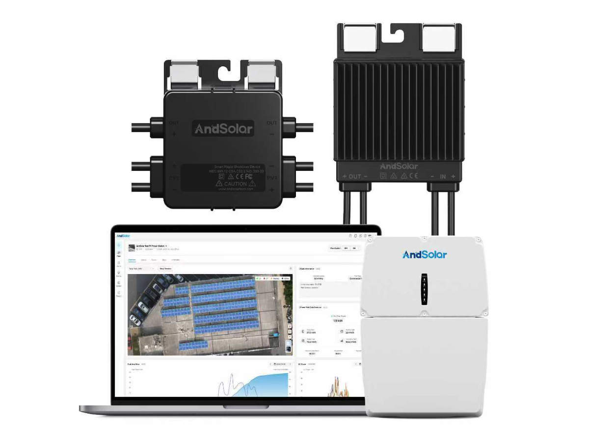
Selecting the right rapid shutdown device for your photovoltaic array is a critical decision that directly impacts safety compliance, system performance, and long-term operational reliability. As solar installations continue to expand across residential, commercial, and utility-scale applications, rapid shutdown systems have evolved from optional add-ons to mandatory safety components governed by strict electrical codes. The selection process requires careful evaluation of technical specifications, compatibility factors, regulatory requirements, and practical installation considerations. Understanding what to check before committing to a specific rapid shutdown device ensures your PV system meets current code requirements while delivering reliable protection for first responders and maintenance personnel. This article provides a comprehensive framework for evaluating rapid shutdown devices, covering the essential criteria that separate adequate solutions from optimal ones tailored to your specific array configuration and operational environment.
The complexity of modern PV arrays demands a methodical approach to component selection, particularly for safety-critical equipment like rapid shutdown systems. Whether you're designing a new installation or retrofitting an existing array to meet updated code requirements, the checklist approach outlined here addresses voltage control thresholds, communication protocol compatibility, environmental durability ratings, installer accessibility, and future system scalability. By systematically evaluating each factor, you can identify the rapid shutdown device that not only satisfies minimum compliance standards but also integrates seamlessly with your inverter technology, module configuration, and site-specific conditions. The right selection minimizes installation complexity, reduces ongoing maintenance requirements, and provides dependable shutdown functionality throughout the system's operational lifespan.
Understanding Code Compliance and Voltage Thresholds
NEC 690.12 Requirements and Your System Design
The National Electrical Code section 690.12 establishes mandatory voltage reduction requirements that define the baseline functionality for any rapid shutdown device. According to current standards, controlled conductors outside the array boundary must be reduced to 80 volts or less within 30 seconds of rapid shutdown initiation, while conductors more than one foot from the array must drop to 80 volts within 30 seconds and to 30 volts or less within five minutes. These specific thresholds are not suggestions but legal requirements that determine whether your installation passes inspection. When evaluating a rapid shutdown device, verify that the manufacturer provides clear documentation demonstrating compliance with these voltage and timing specifications through certified testing protocols. Many devices exceed these minimum requirements, offering faster shutdown times or lower residual voltages, which can provide additional safety margins particularly valuable in large commercial installations where multiple array sections must coordinate shutdown sequences.
Voltage Rating Compatibility with Your Array Configuration
Your PV array's maximum system voltage dictates the voltage rating requirements for your rapid shutdown device. Residential systems typically operate at 600 volts or below, while commercial and utility-scale installations may reach 1000 volts or 1500 volts depending on string configuration and inverter technology. The rapid shutdown device must be rated for continuous operation at or above your array's maximum DC voltage under all temperature conditions, including cold-weather scenarios where open-circuit voltage increases significantly. Underrating the voltage capability creates immediate safety hazards and compliance failures, while substantial overrating may increase component costs unnecessarily. Check the device's voltage rating across its full operating temperature range, as some manufacturers specify ratings that degrade at temperature extremes. This verification becomes particularly important for ground-mounted arrays in extreme climates where winter temperatures can push open-circuit voltages well above nameplate specifications.
Current Handling Capacity and String Configuration
The continuous current rating of your rapid shutdown device must accommodate the maximum current your array can generate under peak irradiance conditions, including safety factors for transient overcurrent events. Module-level rapid shutdown devices typically handle currents from individual modules ranging from 10 to 15 amperes, while string-level or array-level devices must be rated for the combined current of all parallel strings they control. When checking current specifications, consider not just the nominal operating current but also the device's surge current tolerance and thermal management capabilities during sustained high-output periods. Installations in high-irradiance environments or those using bifacial modules with ground reflection gains may experience higher actual currents than standard test conditions predict. Verify that the rapid shutdown device includes adequate thermal derating information and that its continuous current rating provides at least 125% of the maximum calculated array current to meet code requirements and ensure reliable long-term operation.
Communication Architecture and System Integration
Protocol Compatibility with Your Inverter Platform
Modern rapid shutdown systems rely on communication protocols to coordinate shutdown commands across distributed devices throughout the array. The rapid shutdown device you select must use a communication standard compatible with your inverter and overall system architecture. Powerline communication protocols transmit shutdown signals over the existing DC wiring infrastructure, eliminating the need for separate control cables but requiring careful attention to signal integrity and noise immunity. Wireless protocols offer installation flexibility but demand verification of signal strength and reliability across your entire array footprint, particularly in installations with metal roofing or other RF-blocking structures. Some advanced rapid shutdown devices support multiple communication methods, providing redundant pathways that enhance system reliability. Before finalizing your selection, confirm that the rapid shutdown device has been tested and certified for interoperability with your specific inverter model, as protocol variations between manufacturers can create integration challenges that surface only after installation is complete.
Module-Level versus Array-Level Control Architecture
The choice between module-level rapid shutdown devices integrated with power optimizers and array-level or combiner-level rapid shutdown devices affects both system cost and operational characteristics. Module-level rapid shutdown device implementations provide granular control and monitoring capabilities, allowing individual module shutdown and facilitating detailed performance diagnostics. This architecture typically costs more per watt but delivers enhanced safety by ensuring voltage reduction occurs immediately at each module, regardless of series string length. Array-level rapid shutdown systems use centralized control devices that manage entire strings or combiner sections, reducing component count and installation labor but requiring more complex wiring configurations to meet code-compliant voltage boundaries. When checking which architecture suits your application, consider factors including array size, rooftop complexity, shading patterns that might benefit from module-level monitoring, budget constraints, and maintenance accessibility for future service needs.
Response Time and Fault Handling Characteristics
The rapid shutdown device's response characteristics determine how quickly and reliably it can reduce array voltage when triggered by manual activation, inverter commands, or fault detection systems. Measured from initiation signal to verified voltage reduction, response time specifications should clearly document worst-case scenarios including maximum cable lengths, extreme temperatures, and aging component conditions. Faster response times provide enhanced safety margins, particularly important in large arrays where signal propagation delays can accumulate across multiple device stages. Additionally, check how the rapid shutdown device handles fault conditions including communication loss, power supply interruption, and partial system failures. Well-designed devices default to the safe shutdown state when communication is lost or power to control circuits is interrupted, ensuring that system failures do not compromise safety functionality. Request test data demonstrating the device's behavior under fault conditions and verify that it meets fail-safe design principles appropriate for safety-critical equipment.
Environmental Durability and Installation Environment
Ingress Protection Ratings for Your Mounting Location
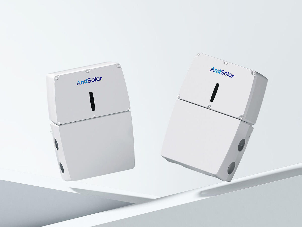
The physical environment where your rapid shutdown device will be installed dictates minimum ingress protection requirements that ensure reliable operation throughout the system's lifespan. Rooftop installations expose devices to direct weather including rain, snow, temperature cycling, and UV radiation, typically requiring IP65 or IP67 ratings that provide complete dust protection and resistance to water jets or temporary immersion. Ground-mounted arrays in agricultural or desert environments face additional challenges from dust accumulation, vegetation contact, and potential physical impacts that may justify higher protection ratings or supplementary enclosures. When checking ingress protection specifications, verify that the rating applies to the installed configuration including all cable entries and mounting interfaces, not just the device enclosure in laboratory conditions. Some rapid shutdown devices achieve high IP ratings only when specific cable glands or mounting accessories are used, creating potential vulnerabilities if installation practices deviate from manufacturer specifications.
Operating Temperature Range and Thermal Management
Rapid shutdown devices mounted on rooftops or in direct sun exposure experience extreme temperature conditions that can reach 75°C to 85°C during summer peak hours, while winter installations in northern climates may encounter temperatures below -40°C. The device's specified operating temperature range must encompass these extremes with adequate margins, as thermal stress accelerates component aging and can trigger premature failures in underspecified equipment. Check whether the manufacturer provides derating curves that show how voltage and current handling capabilities change with temperature, as many electronic components reduce their safe operating limits at elevated temperatures. High-quality rapid shutdown devices incorporate thermal management features including heat sinks, thermal interface materials, and intelligent power limiting that prevents self-damage during sustained high-temperature operation. For installations in extreme climates, request accelerated aging test data and field reliability statistics that demonstrate the device can maintain shutdown functionality after years of thermal cycling.
UV Resistance and Material Degradation Factors
Plastic enclosures and cable insulation materials used in rapid shutdown device construction face continuous ultraviolet radiation exposure in outdoor installations, potentially leading to embrittlement, cracking, and moisture infiltration over time. When evaluating device durability, check that enclosure materials are rated for outdoor UV exposure with industry-standard tests such as ASTM G154 or equivalent accelerated weathering protocols. High-quality devices use UV-stabilized polymers or metal enclosures that resist degradation, while value-engineered alternatives may show acceptable initial performance but deteriorate significantly after several years of sun exposure. Cable entry points represent particular vulnerability, as UV-degraded cable jackets can allow moisture penetration even when the main enclosure maintains integrity. Verify that all external components including mounting brackets, cable glands, and connector housings are specified for long-term outdoor use and that the manufacturer offers warranty coverage commensurate with the expected 25-year system lifespan.
Installation Practicality and Maintenance Accessibility
Mounting Configuration and Roof Integration
The physical mounting requirements for your rapid shutdown device affect installation labor costs, roof penetration counts, and long-term weatherproofing reliability. Module-level devices integrated with mounting clips or frame attachments minimize additional roof penetrations but may complicate future module replacement or system reconfiguration. String-level or array-level rapid shutdown devices typically mount to racking systems or in separate junction boxes, requiring dedicated mounting locations with appropriate structural support and accessibility for maintenance. When checking mounting specifications, consider the device's weight, mounting footprint, cable entry locations, and required clearances for thermal dissipation and maintenance access. Some rapid shutdown device designs integrate directly with specific racking systems through proprietary mounting interfaces, potentially limiting future system modifications or requiring complete replacement if racking upgrades become necessary. Evaluate whether the mounting approach aligns with your installation's structural capabilities and whether it facilitates or complicates future service activities including firmware updates and component replacement.
Wire Management and Connection Methodology
The wiring interface design of your rapid shutdown device significantly impacts installation time, connection reliability, and troubleshooting accessibility. Push-in connectors or spring-clamp terminals enable tool-free connections that reduce installation time and eliminate torque-related reliability concerns, but may require specific wire preparation techniques and limit wire gauge options. Traditional screw terminals provide universal compatibility and field-proven reliability but add installation time and require periodic retorquing to maintain connection integrity over thermal cycling. When evaluating connection methodology, check whether the rapid shutdown device accommodates the wire gauges used in your array design and whether termination can be performed reliably while wearing electrical safety gloves. Some devices provide clear labeling and color-coding that simplifies polarity verification and reduces installation errors, while others present connection terminals that are difficult to access or prone to confusion between multiple devices in close proximity. Request installer feedback from field technicians who have worked with the specific device to identify practical installation challenges that may not be apparent from specification sheets.
Diagnostic Features and Troubleshooting Support
Rapid shutdown devices with integrated diagnostic capabilities simplify commissioning, ongoing monitoring, and fault diagnosis, potentially reducing maintenance costs over the system's operational life. LED indicators that display operational status, communication health, and fault conditions enable quick visual verification during installation and service visits without requiring specialized test equipment. Advanced devices provide communication interfaces that integrate with inverter monitoring platforms, allowing remote verification of rapid shutdown system functionality and early warning of degraded components. When checking diagnostic features, evaluate whether the information provided enables effective troubleshooting by typical electrical contractors rather than requiring specialized training or manufacturer support. Some rapid shutdown devices include self-test functions that periodically verify shutdown circuit integrity and command responsiveness, alerting operators to developing problems before complete failures occur. Consider whether the diagnostic approach aligns with your organization's maintenance capabilities and whether replacement devices will be readily available if field repairs become necessary.
Future-Proofing and System Scalability Considerations
Firmware Updateability and Technology Evolution
As electrical codes continue to evolve and communication protocols advance, the ability to update rapid shutdown device firmware provides valuable future-proofing against obsolescence. Devices with field-updateable firmware can receive patches for discovered bugs, improvements in shutdown algorithms, and potentially even updates to support revised code requirements without physical component replacement. When checking firmware update capabilities, verify whether updates can be performed remotely through network connections or require on-site access with specialized programming equipment. Some manufacturers provide over-the-air update capabilities through their monitoring platforms, while others require manual update procedures that may prove impractical for large distributed arrays. Evaluate the manufacturer's track record for providing timely firmware updates and their commitment to long-term product support, as firmware update capabilities provide value only if the manufacturer actively maintains and improves their product line throughout its operational lifespan.
Expansion Compatibility and Array Reconfiguration
Many PV installations undergo capacity expansions or module replacements over their operational life, requiring rapid shutdown systems that can accommodate array modifications without complete replacement. When selecting a rapid shutdown device, check whether the communication architecture and control topology support adding devices to existing installations without disrupting operational sections. Some systems use daisy-chain communication topologies that simplify expansion by allowing new devices to be appended to existing chains, while others employ addressed communication schemes that may require controller reconfiguration or capacity upgrades. For installations where future expansion is anticipated, verify that the rapid shutdown device manufacturer maintains consistent product availability and backward compatibility across product generations. The ability to integrate new devices with older installations protects your investment and avoids forced upgrades driven by component obsolescence rather than functional requirements.
Warranty Coverage and Replacement Parts Availability
The warranty terms and replacement parts availability for your rapid shutdown device directly affect long-term ownership costs and system reliability. Standard warranties typically range from 10 to 25 years, with variations in coverage scope including full replacement, prorated coverage, and exclusions for specific failure modes or environmental damage. When checking warranty terms, verify whether coverage extends throughout the anticipated system lifespan and whether the manufacturer maintains financial stability and operational continuity sufficient to honor long-term warranty commitments. Replacement parts availability becomes particularly important for installations using array-level or string-level rapid shutdown devices where single-component failures can affect significant array sections. Manufacturers with established distribution networks and commitment to long-term parts inventory provide better assurance that failed devices can be replaced promptly without extended system downtime. Request information about the manufacturer's installed base, market presence duration, and field reliability statistics that indicate the likelihood of requiring warranty service during your system's operational life.
FAQ
What is the primary difference between module-level and string-level rapid shutdown devices?
Module-level rapid shutdown devices attach to individual solar modules and reduce voltage immediately at the source, providing the most granular control and inherent compliance with voltage boundary requirements since each module can be independently shut down. String-level rapid shutdown devices control entire series-connected strings from centralized locations, typically requiring fewer total components and less installation labor but demanding more careful attention to conductor routing and voltage boundary delineation. The choice between architectures depends on array size, budget, monitoring requirements, and site complexity, with module-level solutions offering superior safety and diagnostics at higher per-watt costs, while string-level approaches provide cost efficiency for straightforward installations with clear conductor boundaries.
Can I add a rapid shutdown device to an existing PV system that was installed before current code requirements?
Most existing PV arrays can be retrofitted with rapid shutdown devices to meet updated code requirements, though the specific retrofit approach depends on your system's inverter type, wiring configuration, and available mounting locations. String inverter systems often require adding string-level rapid shutdown devices in combiner boxes or at inverter connections, along with manual initiation switches at required locations. Microinverter and power optimizer systems may require only control system upgrades if the existing devices support rapid shutdown functionality through firmware or communication updates. The retrofit process typically costs significantly less than complete system replacement and can usually be completed without removing modules or extensively modifying racking, though a qualified solar contractor should evaluate your specific installation to determine the most practical retrofit approach and ensure code compliance.
How often should rapid shutdown systems be tested to ensure they remain functional?
Industry best practices recommend testing rapid shutdown device functionality at least annually, with additional testing after any system modifications, severe weather events, or maintenance activities that affect DC wiring or control circuits. Testing procedures typically involve initiating the shutdown sequence through manual switches or controlled system commands, then using voltage measurement equipment to verify that array conductors reduce to code-compliant voltage levels within specified timeframes. Many modern rapid shutdown devices include self-test capabilities that automatically verify circuit integrity without requiring manual testing, though periodic manual verification remains advisable to confirm end-to-end system functionality including initiation switches and emergency procedures. For commercial installations subject to authority having jurisdiction inspections, maintain documented test records that demonstrate ongoing compliance with safety requirements throughout the system's operational life.
What happens to my rapid shutdown device if the main inverter fails or loses power?
Well-designed rapid shutdown devices incorporate fail-safe functionality that defaults to the shutdown state when control power or communication signals are lost, ensuring that inverter failures or power interruptions do not compromise safety protection. This fail-safe behavior means the array automatically shuts down if the inverter stops operating or if control circuit wiring becomes damaged, though it may also result in nuisance shutdowns during temporary power interruptions or communication disruptions. Some advanced rapid shutdown systems include backup power circuits or energy storage that maintains normal operation during brief power interruptions while still providing reliable shutdown during actual failures. When evaluating devices, verify that the fail-safe behavior aligns with your safety priorities and operational requirements, recognizing that maximum safety through automatic shutdown during any anomaly may occasionally conflict with maximum system uptime and energy production goals.
Table of Contents
- Understanding Code Compliance and Voltage Thresholds
- Communication Architecture and System Integration
- Environmental Durability and Installation Environment
- Installation Practicality and Maintenance Accessibility
- Future-Proofing and System Scalability Considerations
-
FAQ
- What is the primary difference between module-level and string-level rapid shutdown devices?
- Can I add a rapid shutdown device to an existing PV system that was installed before current code requirements?
- How often should rapid shutdown systems be tested to ensure they remain functional?
- What happens to my rapid shutdown device if the main inverter fails or loses power?
